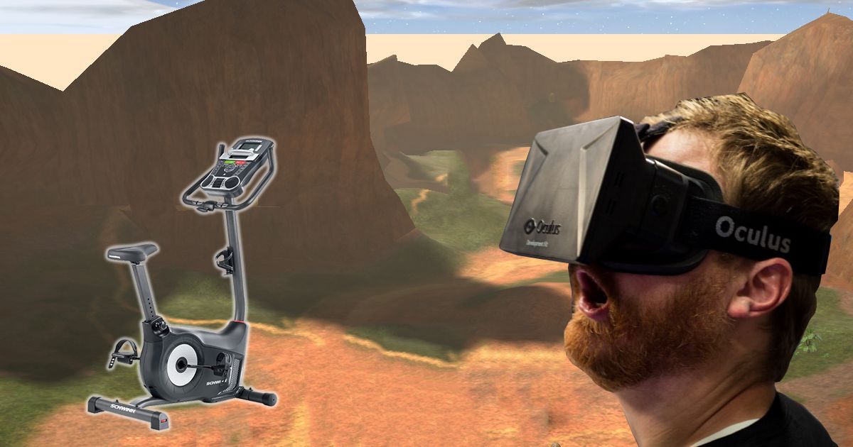
New side project, VR exercise bike (VREB - Part 1)

About 6 months ago after some efforts trying to become more healthy I made the decision to get myself an exercise bike, a Schwinn 130i to be exact. It was relatively affordable for what it offers and even allows me log my data to a USB and upload it to Schwinn Connect. It wasn't too long before the process of plugging the USB into my computer, logging into the website and uploading the .DAT file (which is essentially just a json file) really started to grind my gears. I created a small project called AutoSchwinnConnect. Just sits there in system tray, waits for a USB to be inserted and if it detects the correct data file it logs you in and uploads the data to the Schwinn Connect service (Uploader and system tray icon not included in released code yet). Wasn't really a hack of my equipment, but more of a tool. Had me thinking of what I could do to hack it though.
I remembered back to last year when some friends created a game at a Global Game Jam event called Dreadmill. They had essentially hacked a treadmill and used its inputs for their game. Was curious how I could do the same for my bike. Looking around at what some other people had done I found a blog post about someone who hacked their Schwann A10 and prevented it going into sleep mode during inactivity. Had me thinking of what I could do. VR is becoming more and more popular, and google cardboard or other variants exist and are cheap. I wondered if I could get data from my exercise bike and use it to control how I ride my bike in a VR world.
From when I assembled the bike and I remembered it had some connectors in it that I had to plug into the top control panel. So I popped off its top, took a photo of the connector and hit up a friend who worked on the Dreadmill game.
Explained what I wanted to do and got a sanity check if what I wondered was possible. Can I read data going to/from this connector? He suggested I take a look into getting an Arduino and to be careful not to blow it up by feeding it 9V into its connectors. So a few weeks later all my new toys arrived
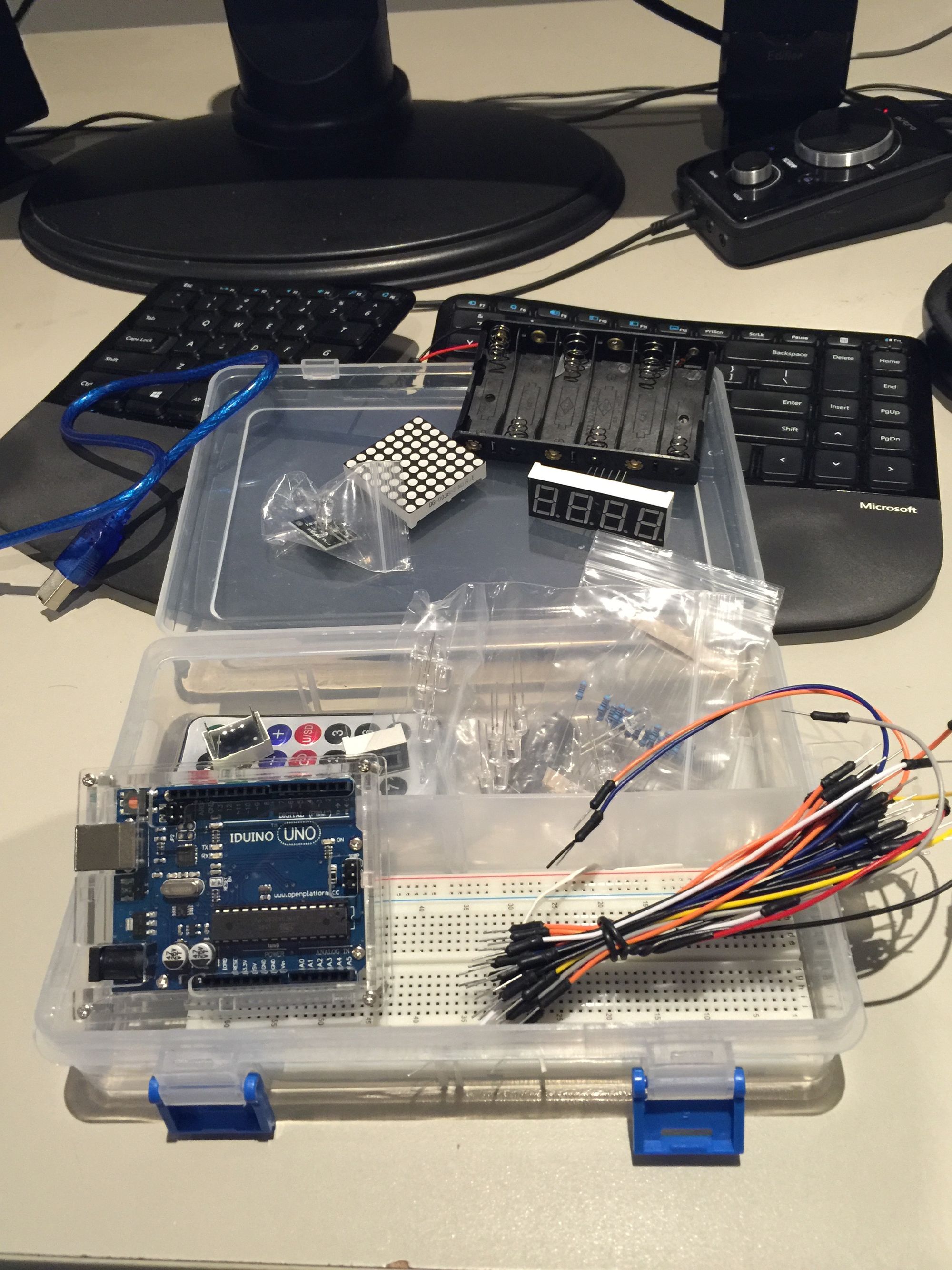
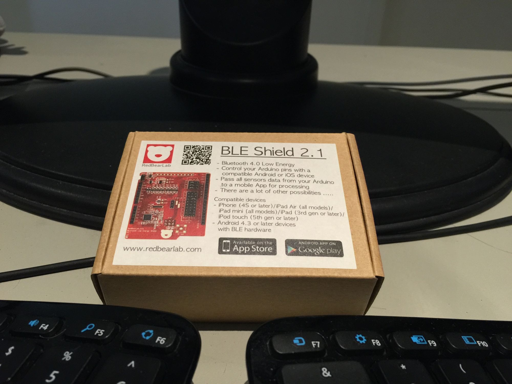
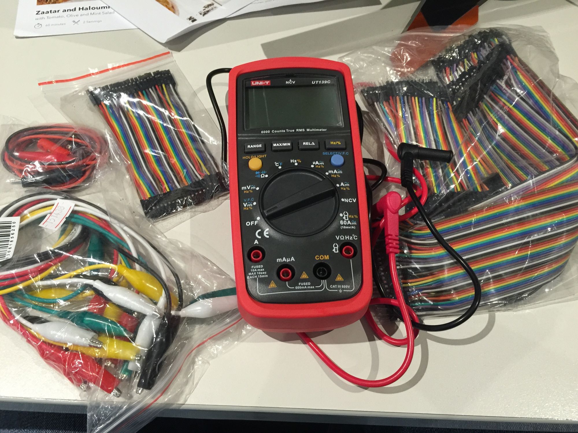
My old $5 multimeter was far from useful. Reading a 9V DC power adapter as 14.3V was not a good sign so I picked up this one. Also some new cables to play with (not necessarily to be used in this project), an Arduino Uno (Iduino Uno for those with a sharp eye) and a BLE Shield. So far my plans are coming together.
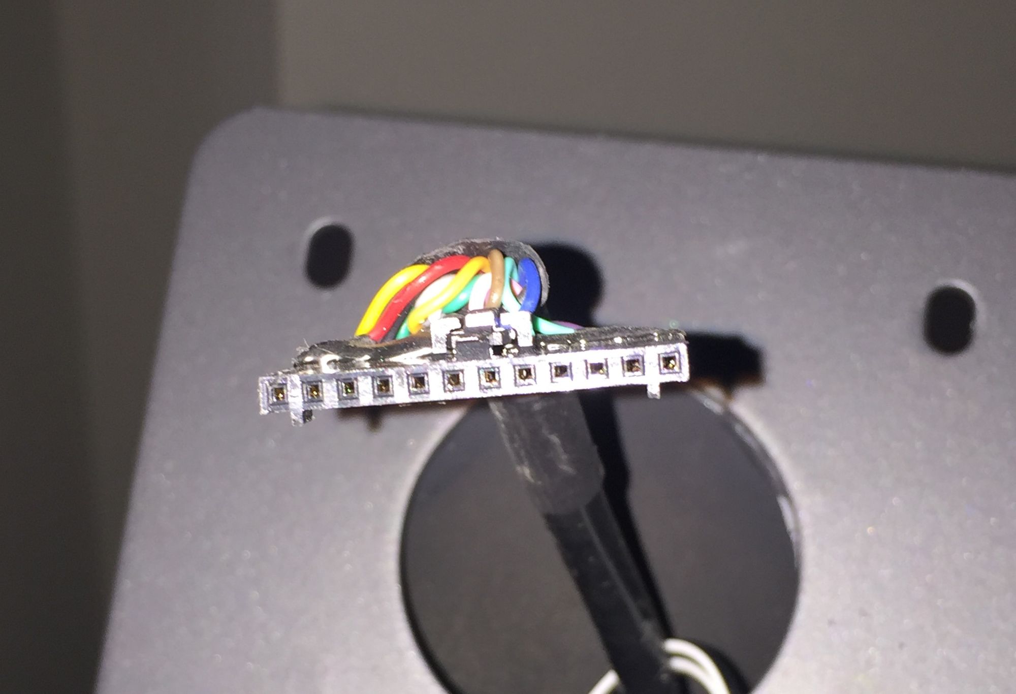
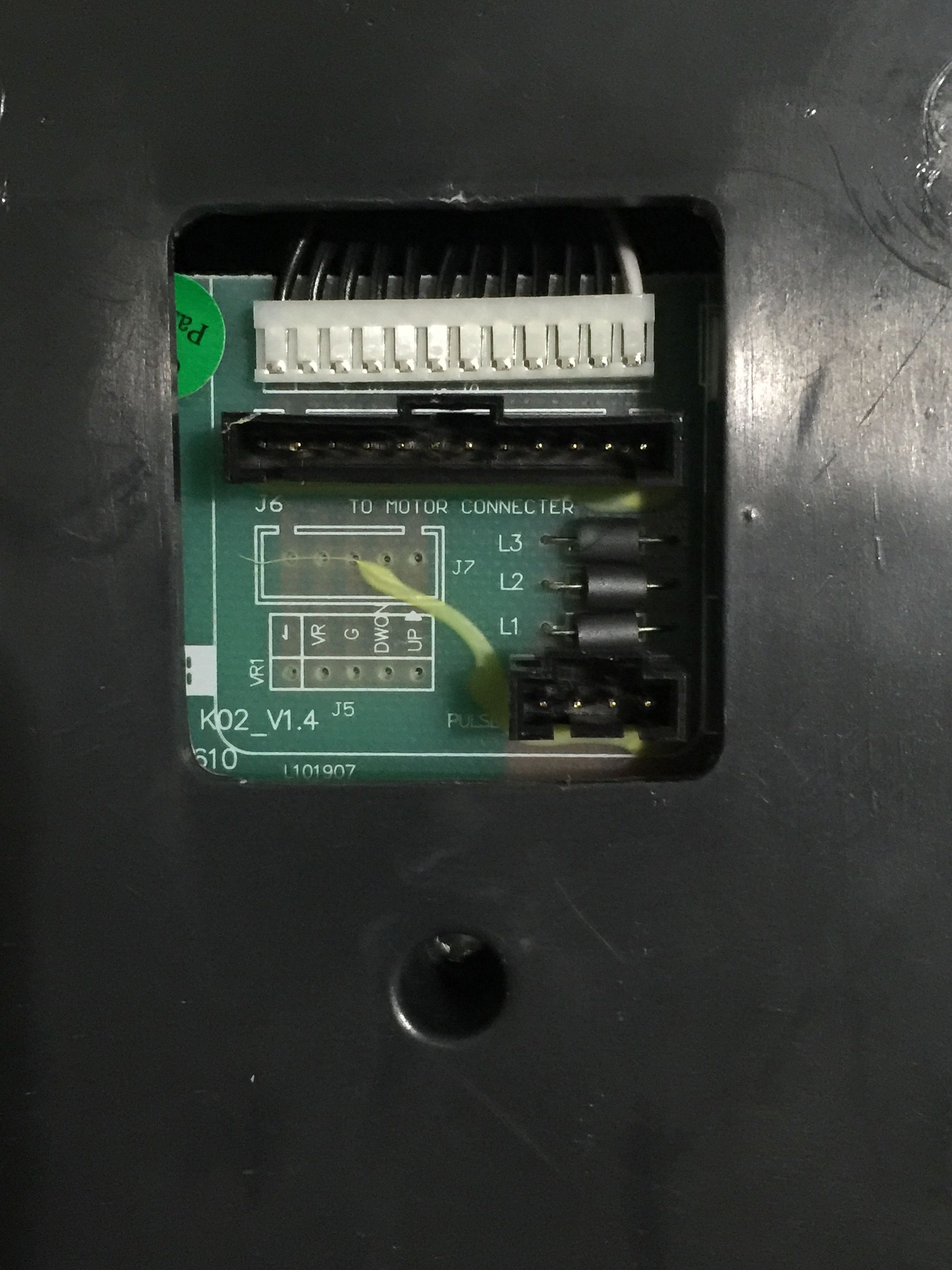
Now to figure out what all these 12 pins do.. Luckily they are somewhat labeled.
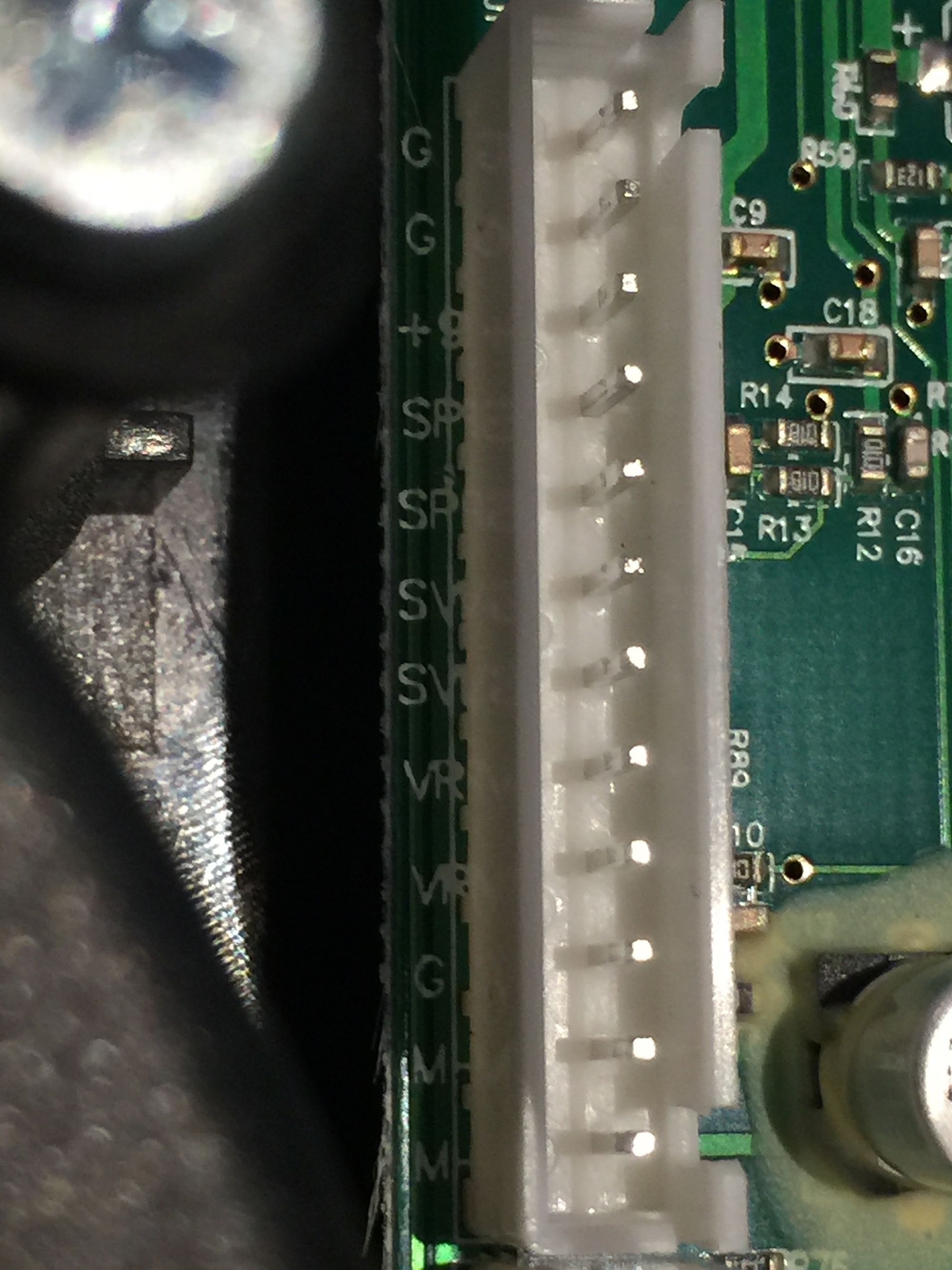
Pins from top to bottom.
1. Ground
2. Ground
3. +9V
4. SPD
5. SPD
6. SVR
7. SVR
8. VR (VRI possibly)
9. VR
10. Ground
11. M
12. M
I did a test for continuity (because it is about as far as my electronics knowledge goes) and I found pins 1 and 2 are connected and pins 11 and 12 are connected. This was tested without power connected to the machine.
I managed to find a digital copy of the manual on ManualsLib which I uploaded for reference. One thing of particular interest was on page 32.
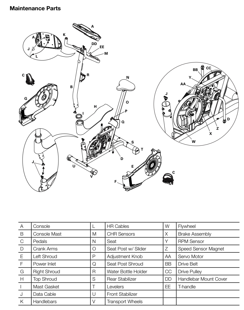
Part Y (RPM Sensor), part Z (Speed Sensor Magnet) and part AA (Servo Motor). Are these the pins SPD for speed sensor magnet, pins SVR for the RPM sensor? I could find out more if I pulled mine apart more and traced the wires. But I'll wait until VREB Part 2 for that.
Back to the control panel, next to this there is an unused 5 pin connector. (I also realised these things are listed on the PCB listed below, maybe for a more advanced unit?)
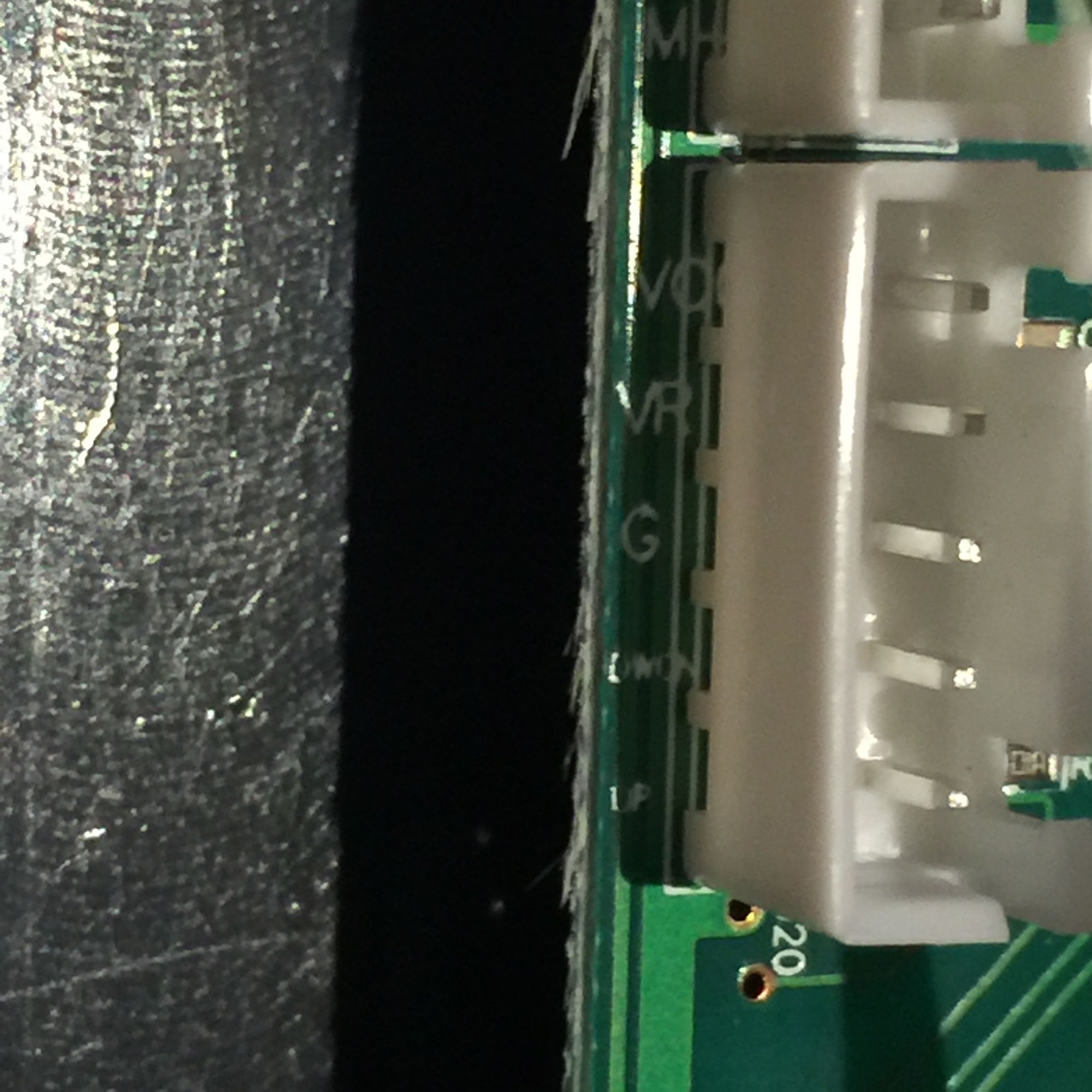
- VO(something)
- VR
- G
- DWON
- UP
And then there is these two 3 pin connectors. One of which goes to the heart rate sensor. What one? Well I didn't realise there was two when I pulled it apart ;)
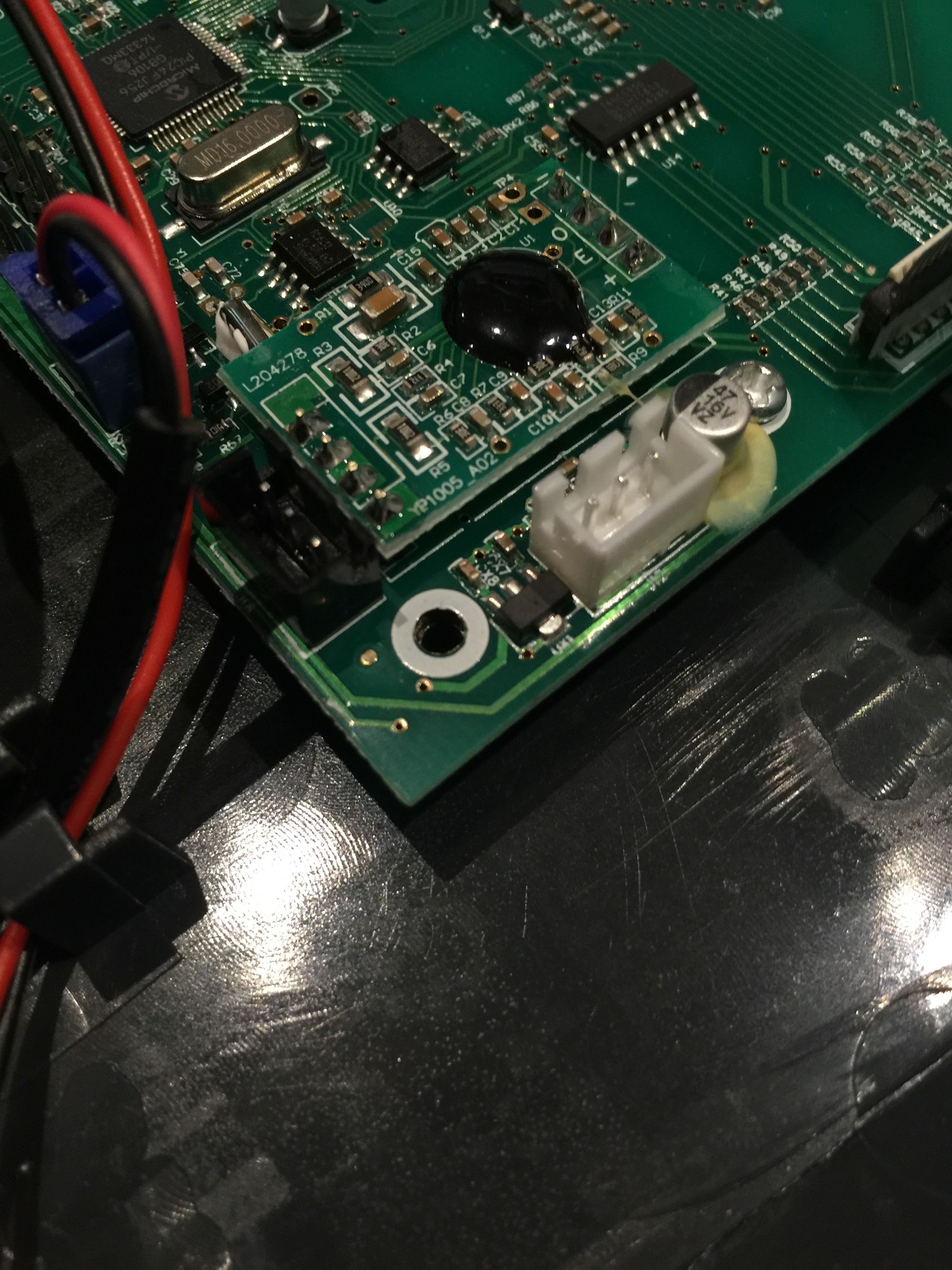
Speaking of that heart rate sensors (and I guess something that may make a lot more sense to any electronic engineers out there so feel free to let me know) is that the internal connector is a 3 pin, but the external connector I would normally have access to during assembly is a 4 pin. There is this little PCB in the middle which has three diodes (I think they are diodes) on it.
But what was interesting to me was the back of them.
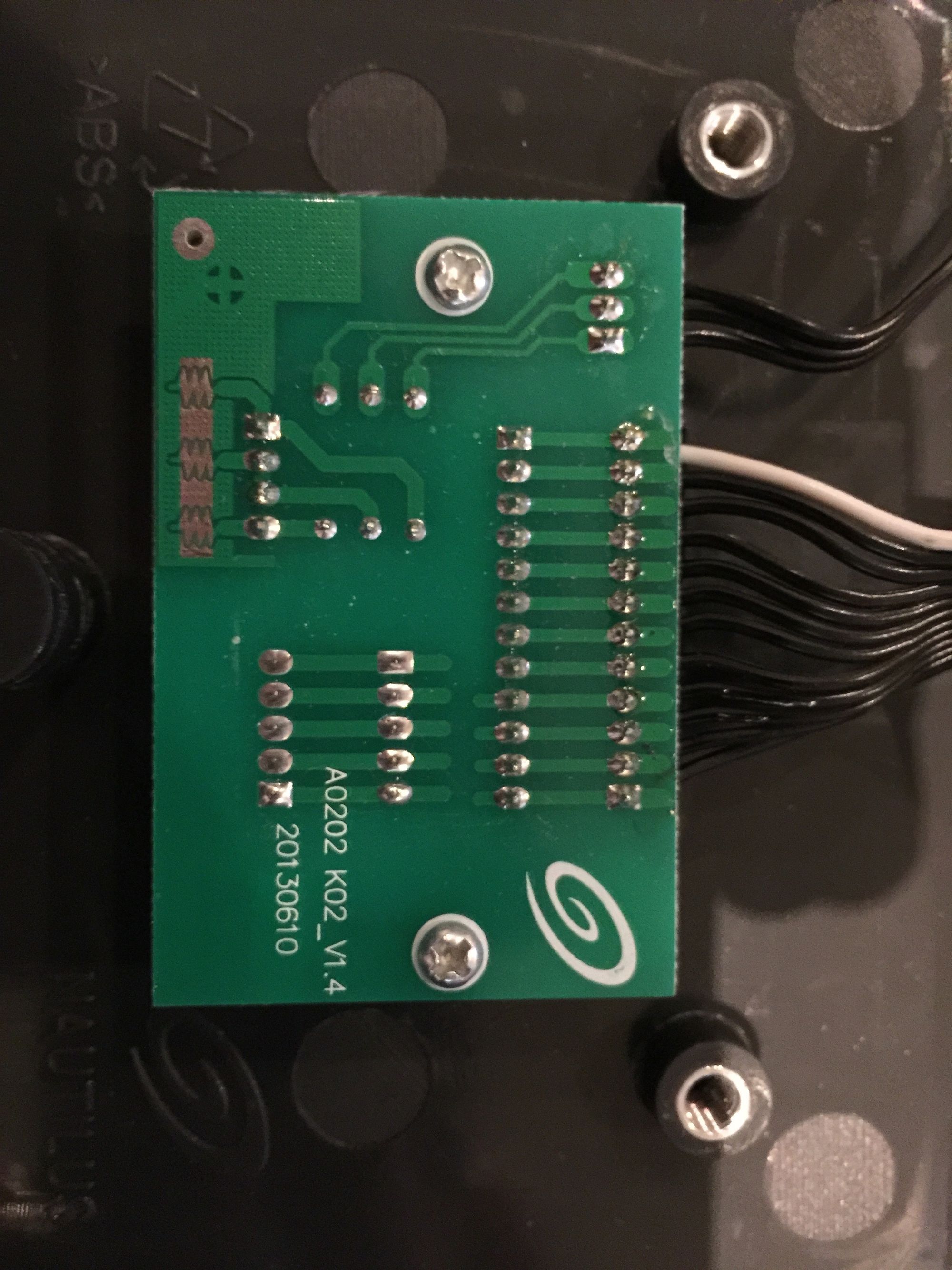
As you can see, of the 4 pins that come in, the middle two are connected together. The cable that goes down the stem to the sensors has cables that are black, black white, black and black white. With one black and one black white going to each sensor. Maybe that makes complete sense to someone as to how they work?
That sums up all the electronics I have, and I have investigated on so far. But jumping back a step, that BLE Shield. Why you may ask? If I can read data from any of these pins I can send them via bluetooth to my phone and vice versa I can send data from my phone through to the device. In theory this will let me monitor speed to relay into the game engine, and then from the game engine monitor slopes in the terrain and relay that to the brakes of the bike making it harder to ride up a hill. But Brad! you exclaim, the latency is terrible! For the purposes of this project I am going to consider anything less than a second useable. From playing around with it so far it appears to be less than half a second.
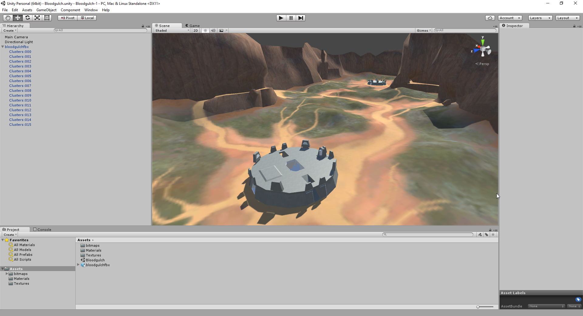
Ok then, how will I display any of that on the screen? Well... Unity has pretty good support for google cardboard so that was mostly a no-brainer (plus I wanted to learn more Unity). What about the 3D environment? Well I did manage to rip this from my favourite games of all time and get it imported into Unity. More to come in part 2.
Featured photo contains imagery of Will Smith, not me, though others may be confused by our awesome beards. Click through to read more about what he is up to https://medium.com/will-smith