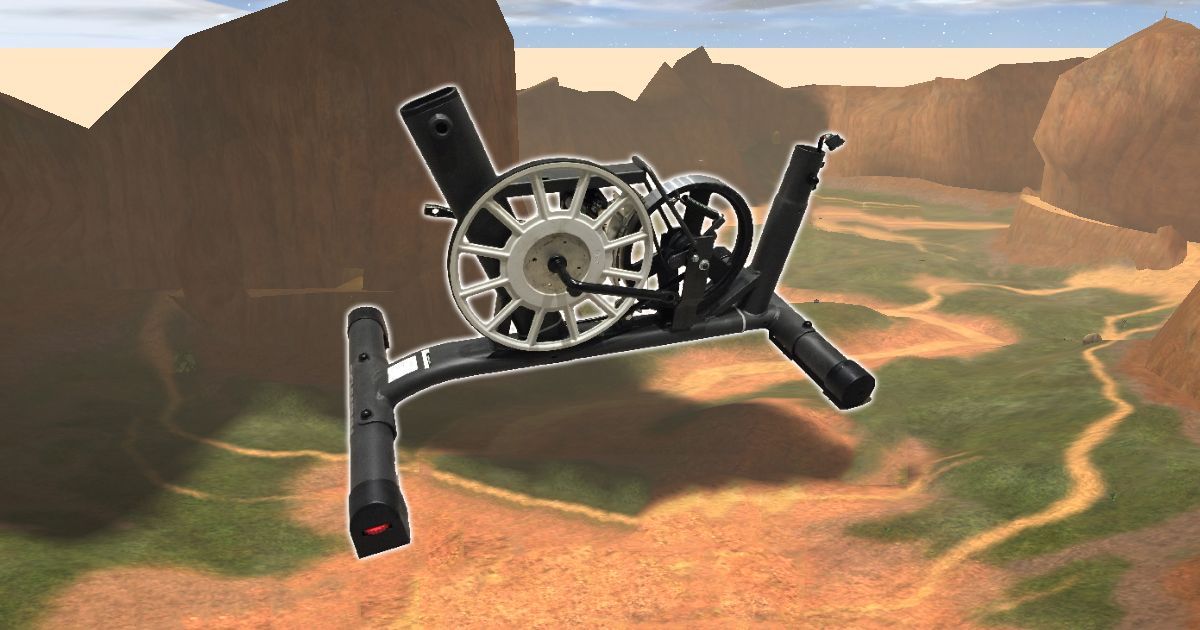
VREB Part 2, time to examine the components

So in the last post I had done a lot of looking around at the circuit board and outlined my plans. Tonight I decided to tinker a little bit more with the bike. It is pretty much disassembled more than how it came from the factory in November 2015.
First, starting from the power adapter input I decided to trace the wire. One thing that stood out to me at first is that the power pack has 2 inputs. Inner pin and outer casing (I'm sure they have proper names) but it connects into a 3 pin connector on the inside. Checking the continuity I found that the two outer pins are for positive and negative as expected. But the center of the there is a negative pin, until you plug in the DC adapter and then it turns into a positive. Reading online this is sometimes used to swap from DC power to battery backup or vice versa. Seems irrelevant here as there is no batteries that can be used in it. I traced these three wires in to the end of our 12 pin connector and found they are pins 1, 2 and 3. Ground, Ground and +9V. Next I spotted this little sensor.
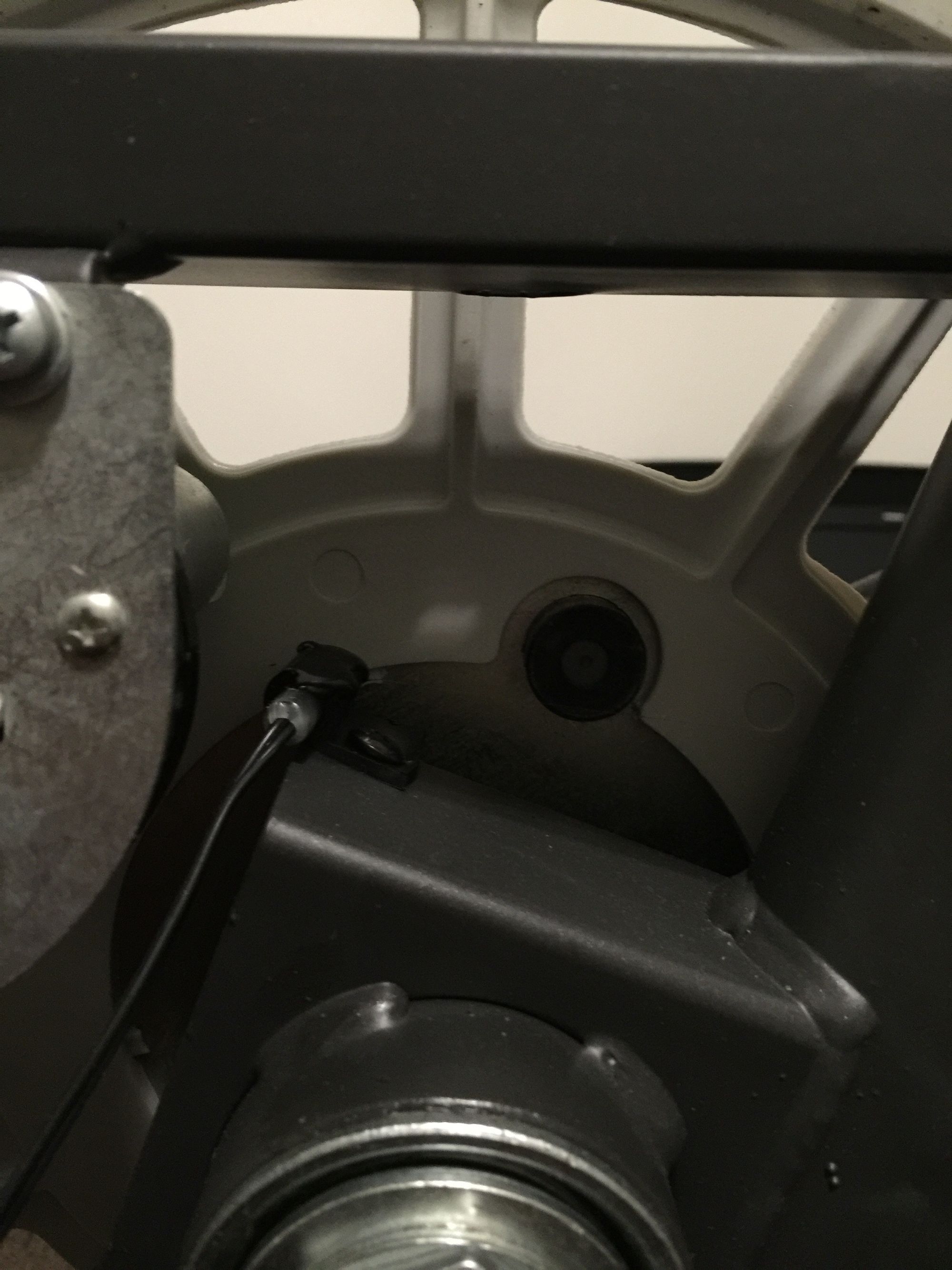
At first glance I thought it was a little switch activated by a magnet similar to a meter wheel with a clicker attached. After a quick google I found this is called a hall effect sensor. According to our manual this is the RPM sensor. This makes complete sense as it is used to calculate the rotations of the crank. Hooked it up to the multimeter and found it closes the circuit as the magnet comes past. The magnet is also on the manual diagram as part Z, speed sensor magnet. Traced its wires and found it is pins 4 and 5. Pin 4 being a black cable with white stripe, and pin 5 being solid black cable.
The next thing that caught my eye was this contraption.
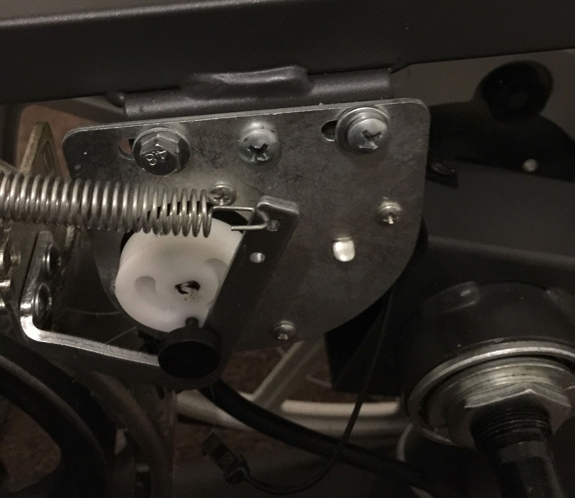
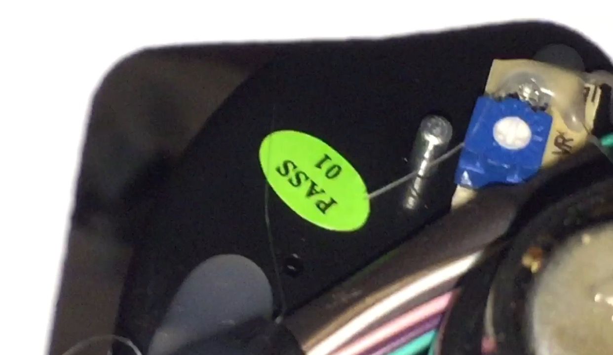
Moving around the back of the device I can see more things going on.
My first thought was, cool, a servo... and... a motor? When I looked up a servo they had 3 input pins just like this so I figured that yes this is indeed a servo. But after more research a photo caught my eye. Before I know it I was knee deep in a blog post from Joe Pitz titled Analog Fix for Nordic Track Exercise Bike. Although our bikes varied a lot, the core mechanics here were identical. That thing with three pins that I called a servo is actually a potentiometer. I should have noticed, it looks identical to the one that came with my Arduino. But again, this makes perfect sense. The computer unit attached to the bike does not adjust motor forward two steps, it goes until the pot reads a certain value so it knows it is in the correct place. I connected the multimeter up to the pot and found it to most probably be 5K-Ohm. I connected the motor to a 5V power source and hooked up my multimeter to measure the resistance. This will come in handy later.
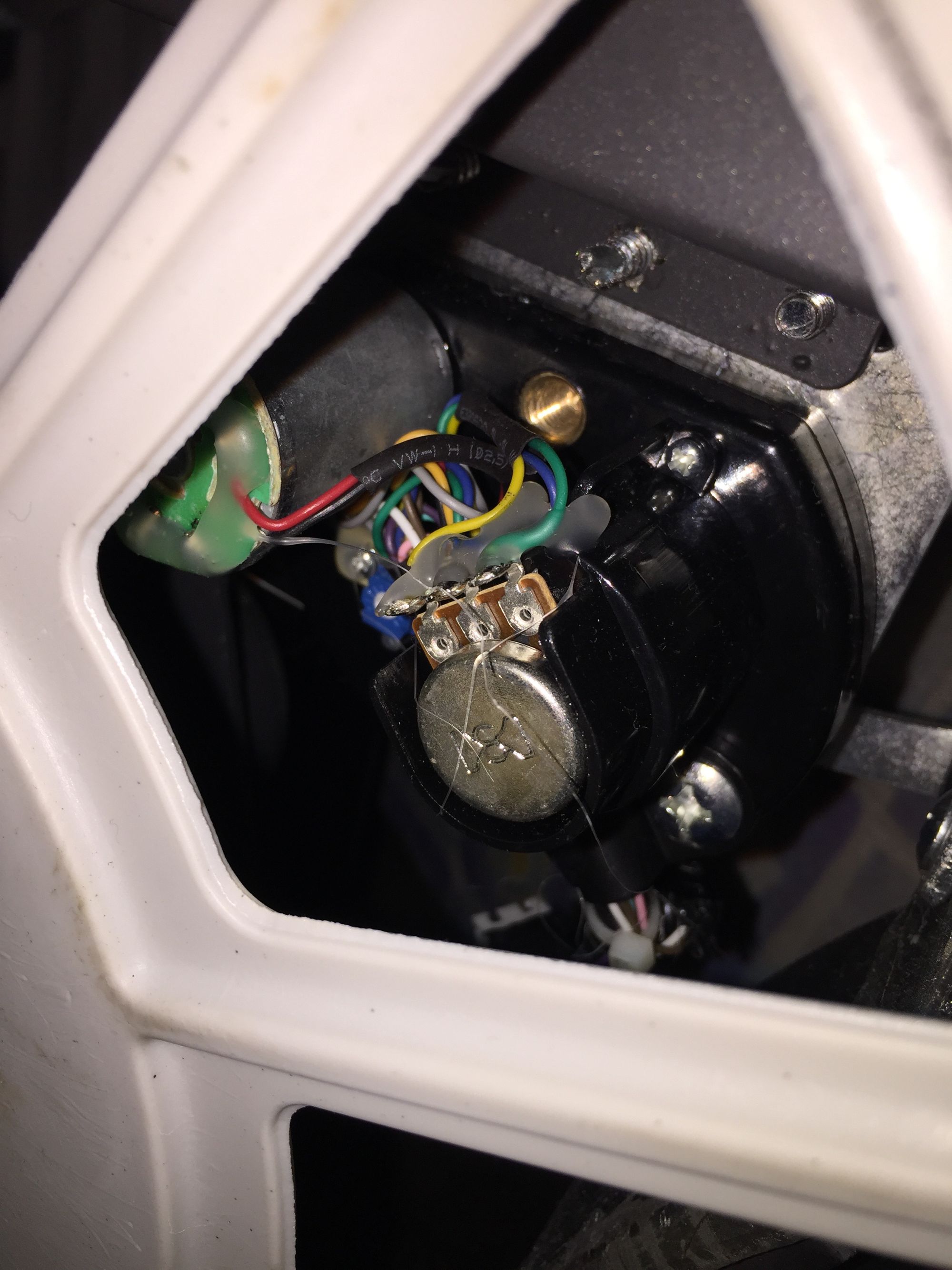
Tracing its wires back I found these to be pins 8, 9 and 10, with 8 being the pin on the far right in the above picture. I tested for continuity with the points available on the back of the motor and found them to be pins 11 and 12. Unsure what one should be called positive and negative. This just leaves pins 6 and 7. From the board they are labeled as SVR. I can not find any other sensors, but I did however find something hidden away. This is the best photo I will be able to get of it and I have no idea what it is for. SVR, VR, voltage regular?
So final summary of our pins.
1. Power pin 1
2. Power pin 2
3. Power pin 3
4. RPM sensor (white stripe)
5. RPM sensor
6. ???
7. ???
8. Potentiometer
9. Potentiometer
10. Potentiometer
11. Motor
12. Motor
With 6 and 7 being labelled SVR still as an unknown. But even without knowing what that thing is, I still have plenty of information to go off.